Gmsh: Creating a Basic Mesh
- Nov 21, 2024
- 3 min read
Gmsh is an open-source finite-element mesh generator, with additional capabilities for pre and post processing. I've used Gmsh in computational fluid dynamics (CFD) to aid in performing simulations using 2D and 3D meshes. This is a basic tutorial on how to create your first mesh.
You'll learn how to use the Gmsh basics, generate a mesh, and refine the mesh in different areas.
Step 1: Download Gmsh for Windows, Linux, or MacOS.
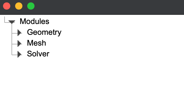
Step 2: Open Gmsh, and familiarize yourself with the left navigation bar. You'll see three main categories: Geometry, Mesh, and Solver. We'll only really worry about the Geometry and Mesh categories for now.
Step 3: Expand the Geometry cateogry, then the Elementary Entities, then the Add category. This will show various different elements that we can add to build our geometry. The most basic elements here are the point and line, which is what we'll be using. However, they all operate fundamentally the same and are used to build a geometry.

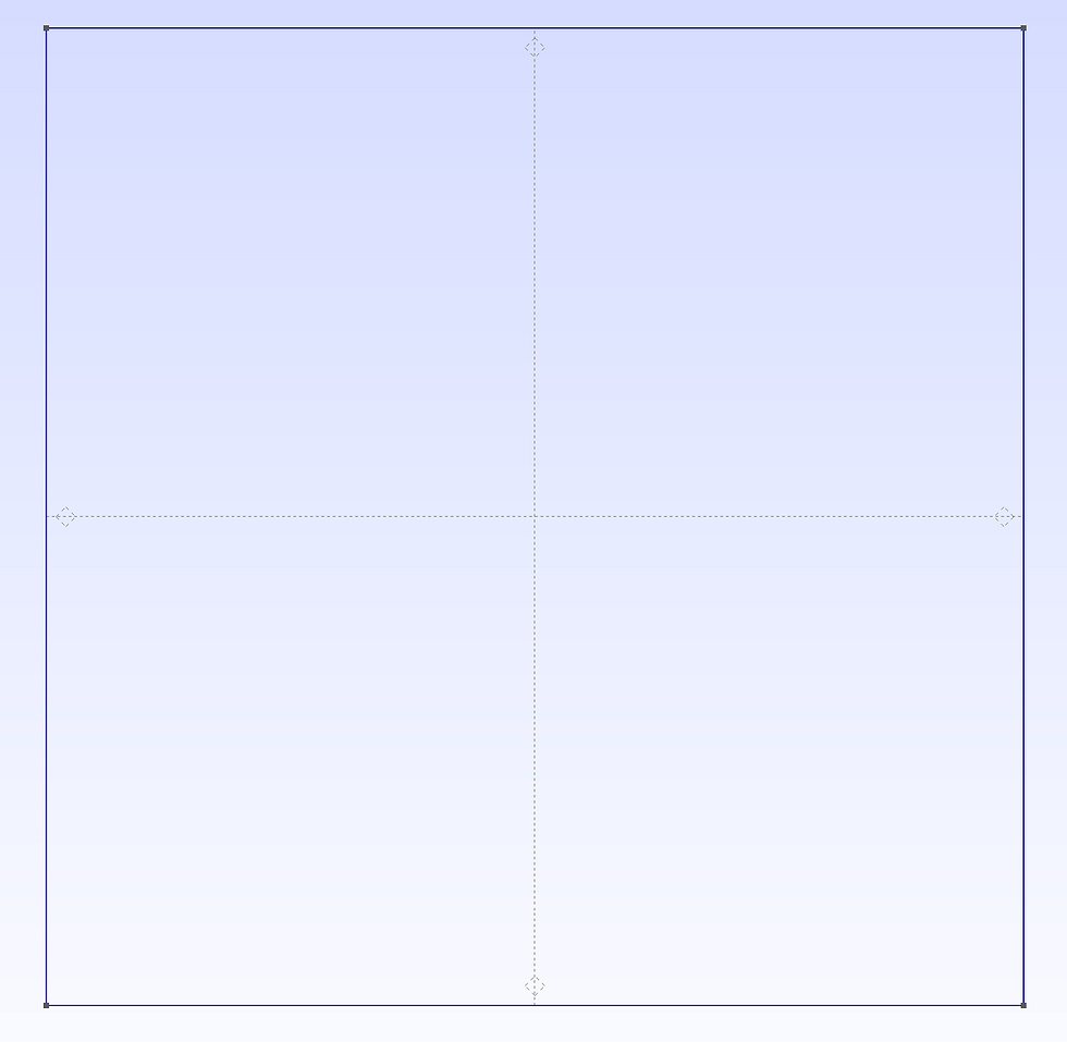
Step 4: Adding four points. We'll put four points at the following locations: (0,0), (0,1), (1,1),(1,0). To do this, click on 'Point' as shown above, and move to the canvas and select your points by clicking. Once finished, you can press 'q' to abort / finish. You should be left with something like this (the points are tiny, but are in the corners):

Step 5: Connect the points with lines. You can also toggle off the axes to see better by right clicking (sometimes a double right click) anywhere on the canvas. Select the 'line' from the left navigation bar, and select the starting point, then the end point. This will draw a line between two points. Each time you want to draw a line, you need to select two points. We'll start in the bottom left corner (it's fairly arbitrary which order you do this in for now), and go around until we have a box. It should look like this:

Step 6: An easier to way to create and edit these points is by looking at the left navigation bar, and clicking 'Edit Script'. This will open a TextEdit view where you can see exactly what happened when we used the Gmsh interface. You can edit this freely, just make sure you save before quitting the TextEdit and then press 'Reload Script' on the left navigation bar. You will use this a lot. Lets add a mesh size parameter 'size' as shown, and edit the script to look like this (once done, press reload script):

Step 7: Add a 'Plane Surface' from the left navigation bar. You will select one of the lines of your box and it will create a plane surface (Make sure after clicking on the line, press 'e' to end selection and then 'q' to abort). You should be left with this:
Step 8: Finally, expand the 'Mesh' category, and press the '2D' option - you'll see your mesh actually show up now!

Step 9: To refine your mesh size, 'Edit Script' and change your size parameter. You can also add an additional size parameter to have the mesh density be different at various points in the mesh. This can obviously be very useful depending on what you're working on. Where, in one area you may need a very fine mesh, whereas another part you may only need a coarse mesh.

In this example, you can see how the mesh is much finer in the top right and bottom left corners, and more coarse in the top left and bottom right. To do this yourself, copy and paste the full code below.
size = 0.1; sizeSmall = 0.01; //+ Point(1) = {0, 0, 0, sizeSmall}; //+ Point(2) = {1, 0, 0, size}; //+ Point(3) = {1, 1, 0, sizeSmall}; //+ Point(4) = {0, 1, 0, size}; //+ Line(1) = {1, 2}; //+ Line(2) = {2, 3}; //+ Line(3) = {3, 4}; //+ Line(4) = {4, 1}; //+ Curve Loop(1) = {3, 4, 1, 2}; //+ Plane Surface(1) = {1}; |
Comments