Automated Insulation Wrapping Machine
AUGUST 2023 - MAY 2024
MECHANICAL: CAD, rapid prototyping, design for manufacturability, manufacturing with mills & lathes
SOFTWARE: Python, C, C++, version control
CU Physics is working with Advanced Conductor Technologies to develop high temperature superconducting cables for high-current power systems and high-field magnets. Our team was tasked with developing an insulation wrapping machine capable of wrapping these cables in a dielectric film. Our machine minimized the number of defects in the insulation, ultimately improving cable performance.
I was responsible for the design of the spool holder system as well as all of the electronics and software.

100+ custom machined components
200+ hours in the machine shop
1000+ components in assembly
180 RPM max speed
DESIGN AND REQUIREMENTS

✓ Variable tension from 2-15 N
✓ Apply film at angle from 20º - 70º
✓ Accomodate manufacture spool tolerance
✓ Support film widths from 0.16"-1"
✓ Rotate up to 180 RPM
✓ Hold two spools simultaneously
✓ Accommodate cable diameters from 0.1"-0.63"
✓ Minimize defects in film application
SUB ASSEMBLIES
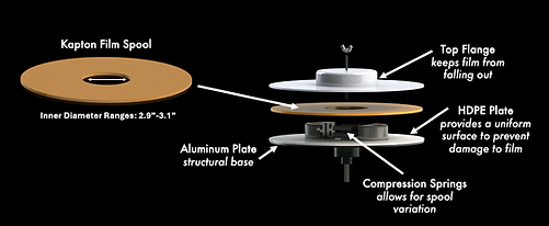
SPOOL HOLDER
The Tape Spool Holder is designed to securely house Kapton tape spools while minimizing weight to accommodate the torque limitations of the tension mechanism. It features a lightweight aluminum base with HDPE plates to prevent the tape from catching on sharp edges. Compression springs housed in Delrin semi-circles accommodate variability in the spools' inner diameter, ensuring the spools remain in place during winding. To address low friction between the Delrin and the spools, high-friction tape is added to the semi-circles. The spool holder connects to the magnetic brake via a custom shaft attachment.

TENSIONING SYSTEM
The tape tensioner system provides precise tension control to the Kapton film, using magnetic brakes capable of applying tension even at low or zero RPM. These brakes function by magnetizing fine stainless-steel powder, ensuring low wear and smooth operation. The system allows for accurate, stable tensioning throughout the winding process, with torque and RPM carefully modeled to ensure the brakes operate efficiently without overheating. To maintain optimal performance, the spool holder's weight is minimized, and the brakes are positioned to reduce the load on the shaft. Additionally, a follower arm potentiometer tracks the spool's size in real time, helping to adjust tension dynamically as the spool diameter changes.

DRIVETRAIN
The drivetrain turns the central tube, which supports the winding head, and was designed for precision with minimal deflection. To rotate the winding head at 180 rpm, we calculated that a 300W motor paired with a worm gearbox would meet the low-speed, high-torque requirements while resisting movement when idle. The motor drives the system through a V-belt and pulley assembly, with the shaft supported by self-aligning pillow blocks for smooth rotation. The central tube was custom-machined for a precise fit to ensure stability and reduce deflection.

ANGLE ADJUSTMENT
The angle adjustment mechanism controls the application angle of the Kapton film, which, along with cable feed speed, determines the overlap of each layer during winding. The entire spool assembly, including the spool holder and tensioning system, is mounted on this mechanism. A linear actuator automatically adjusts the angle, ensuring precise control while the winding head is static to avoid exceeding load limits. The actuator moves carriages on linear guide rails, changing the film's angle of application. The assembly is mounted securely, and the actuator's back drive force prevents unwanted movement during operation, ensuring stable and consistent tension application.
SOFTWARE & EMBEDDED SYSTEMS

The software and embedded systems in our project are powered by three main power supplies: a 24V DC power supply for the drive motor, actuator, and general system power, along with two separate control current power supplies for independent control of the magnetic brakes. These supplies feature 0-10V analog inputs, which are controlled via software PWM from a Raspberry Pi.
The actuators, including the drive motor and linear actuator, are controlled by dedicated controllers: the linear actuator control board (LAC) from Actuonix and a motor controller sourced from Amazon for the drive motor. An emergency stop button is also integrated, which cuts power to the drive motor via a relay when pressed, ensuring safety during operation. The Raspberry Pi can monitor the state of the emergency stop button, although this functionality was not used in testing.
A custom PCB was designed to handle inputs and outputs between the Raspberry Pi and the system’s components. The PCB includes an ADC for converting analog signals (like the follower arm potentiometer) to digital signals, and an amplifying op-amp circuit for converting the Raspberry Pi’s PWM signal to a 0-10V analog output for the magnetic brake power supplies. The PCB was designed for modularity and ease of assembly, using through-hole components and a 12V rail powered by a buck converter.
The ADC converts signals for the follower arm potentiometer, while the op-amp circuit smooths the PWM signal to control the brake power supplies. The Raspberry Pi manages various components, including the drive motor, linear actuator, and emergency stop button. The PCB also includes headers and screw terminals for easy connectivity to these components.
Wiring for the system follows a color-coded scheme to distinguish between power, ground, and PWM signals, ensuring clarity during assembly. Components like the slip ring, potentiometers, and brakes follow a similar color system, with Molex connectors used to prevent incorrect connections. The system’s wiring allows for straightforward setup and avoids mismatches during calibration and software configuration.
Finally, the Raspberry Pi pinout controls key functions like the drivetrain encoder, cable feed encoder, linear actuator, and the emergency stop monitoring. While the pinout for some components (like the encoders) can be adjusted, hardware PWM and ADC pins are fixed. Overall, the software and embedded systems were designed for flexibility, safety, and precise control of the winding head system.
Documentation and Readable Code
Case Study: Linear Encoder
Clear, well-documented, and readable code is essential for effective collaboration, maintenance, and scalability. In this case study, the code demonstrates these principles through consistent formatting, meaningful variable names, and detailed inline comments. Each section is clearly labeled, outlining the purpose of the code and how it functions, making it easy for future developers or team members to understand its behavior. The inclusion of explanations for expected behavior and edge cases, along with a structured approach to error handling, further enhances its readability, ensuring that the code remains maintainable and adaptable over time.